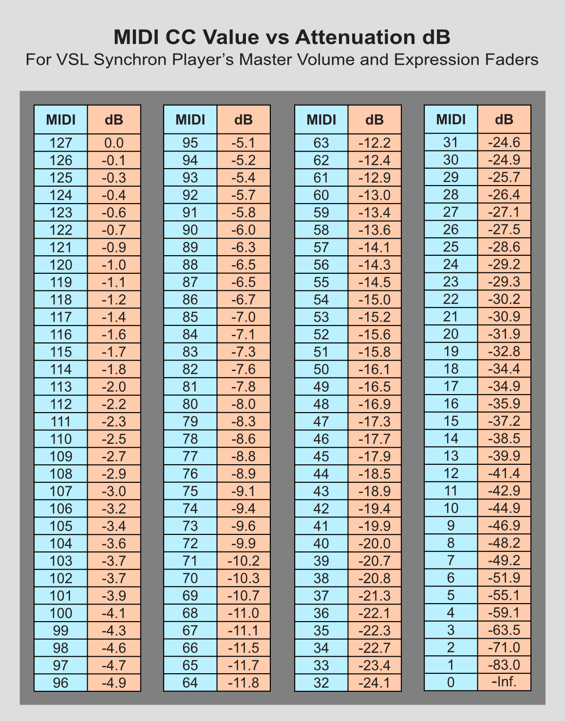
-
Nice one. Did you sync the VOL and EXP fader and used the same CC for both?
I did a similar one for VI some time ago but with varying CC input for VXF and EXP. Pretty useful when you are aiming at a spec. dB interval for your performances. I have gotten used to always trying to fit between approx. -18/-8 dB (depending on the dynamic depth of the performance) to get a good mix.
-
Paolo, most of the credit is rightfully yours - your posts on this topic made me realise something really needs to be done about this issue. So well done, you!
And it's not over yet.
As I mentioned to you in your thread on this topic, I'm going to create some very simple graphics overlaid on an image of the Synchron Volume and Expression faders (as a few alternative ideas for discussion), which I'll post. Then hopefully, if enough users agree on one partilcular graphics scheme, we might then be able to lobby and nudge VSL into adding some similar graphics in a future Synchron Player.
What I have in mind is simply to add a few dB numbers in between these two faders, showing something like, for example, +6, 0, -6, -12, -20 -40, ∞, vertically, with a small dot or dash on both sides of each of these numbers to mark exactly where the faders should be for these dB levels. (I know SSL don't show + or - on their dB markings next to each fader, and I agree with that; I've added them here merely for clarity in our textual context.)
There are a few alternatives to consider, such as 10, 5, 0, 5, 10, 20, 40 .... etc. But the most important thing to keep in mind is that we must work with the existing CC/dB fader curve. If VSL were to update to a different fader curve, imagine the mayhem that would ensue with many users complaining that their previous project mixes are now out of balance as a result of the curve change!
When we're settled on a particular graphical dB legend, then of course I'll change the dB numbers in my graph and table accordingly (unless VSL have by then provided their own graph and table in the documentation!).
Finally, let me emphasise that faders have always been, right from the earliest days, merely variable attenuators. Changing what we regard as our dB calibration on these faders makes ablsolutely no difference to what the fader actually does - it attenuates; pure and simple; it does not amplify. (But you already know that, Paolo; I'm addressing other potentially interested users in general.)
-
Jhonny, I had been wondering if a saintly pro had already done this for the VI Pro Player. Well done, Sir! And your working range of dB does indeed make good sense to me.
All I did with the Expr fader was check that it produces exactly the same attenuation (to 0.01 dB precision) as the Vol fader, at several different CCvals spread across the range. Judging from the results of these spot checks, I felt it reasonable to assume the whole data set would be identical for both faders - as one would expect. I also checked a couple of combinations of both faders to confirm that their dB attenuations do ideed simply sum. Then I used only the Vol fader to generate the full data set, while the Expr fader was kept at 127.
-
Very useful completion, Macker! Now, I'm yet with the doubt of how the Volume and Expression logarithmic scales interact! Paolo
As I said earlier Paolo, it’s a percentage of a percentage, ignoring the discussion about logarithmic scale for a sec, that makes the discussion more complicated to calculate what the actual percentages would be. As I asked earlier l, what are you trying to accomplish with this info?
-
I also think you’re getting into the weeds with the discussion about the db measurements and logarithmic scaling. Db’s are expressed already on a logarithmic scale compared to actual Audible amplitude. So even though the fader on your daw shows db’s being reduced at a faster and faster rate as you take the fader down, if you close your eyes and just move the fader down slowly at a consistent rate it will not sound like it’s accelerating the fade out. It will sound smooth and linear. From that perspective a simple percentage is fine, convert cc values into a simple percentage of amplitude reduction via dsp. A db meter will measure that change as if it’s accelerating logarithmically because the db measured value itself is a ratio that has a logarithmic value.
The two controls are simply a percentage of a percentage of amplitude reduction. Once you know the final total percentage reduction of amplitude per above, then you can compute logarithmically the expected db measurement.
Put another way:
final percentage = (cc11/127) x (cc7/127)
-
As I asked earlier l, what are you trying to accomplish with this info?As I explained in the other discussion ("Volume and Expression"), I’m trying to compensate between the two level controls. Using a percentage, with the formula I proposed, seems empirically to work in small level changes. A more solidly founded theory would be welcome, and the experiments of Macker are supplying data to this.
Paolo
-
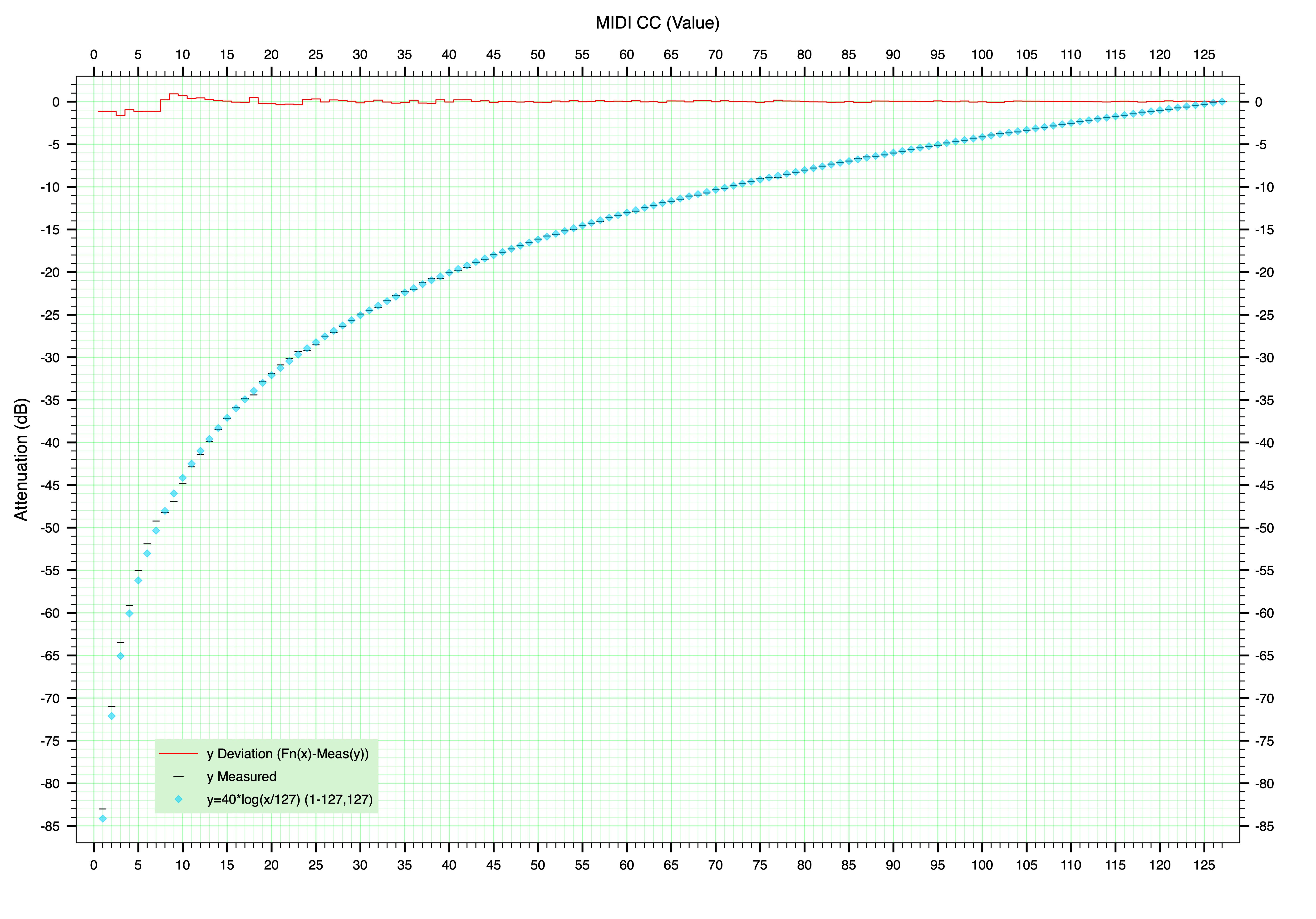
Just for the sake of completeness - and strictly for the mathematically minded among us (I know I know, sorry!) - I've attached a graph showing measured results and calculated results plotted together, the latter using a simple transfer function that I think is probably behind VSL's calibration of the Master Volume and Expression faders.
This posited transfer function can be expressed as:
1. dB = 40*log(CCval/127)
2. CCval = 127*(10^(dB/40))
The graph also plots deviation of measured results from calculated results. I think it fair to say VSL's calibration scheme for these main faders is sensible, reasonable and practical - as usual of course.
[UPDATE 18 Aug]
Out of idle curiosity, I wondered what sort of accuracy I could get by approximating the highest part of the fader curve with a straight line. One example I came up with allows a straight-line law to cover 0dB to -10dB attentuation, allowing CCvals to calculate dB to within a max error range of ±0.5dB. Not too bad! Maybe useful if the only calculator you happen to have at hand doesn't do scientific functions, and you're working within the top 10 dB of these faders.
This straight-line law is:-
1. dB = (0.1811 * CCval) - 22.5 (for CCvals between 70 and 127) (dB >0 should be 'rounded' to 0)
2. CCval = (dB + 22.5) / 0.1811 (for dB between -10 and 0) (CCval ≥ 124 should be 'rounded' to 127)
The combined effect of the two faders faders is simply the sum of their individual attenuations in dB, or:-
dB(combined) = (0.1811 * (CCval1 + CCval2)) - 45
But ........... whatever. In real, practical, everyday terms, all I've put into this thread is just daft! Solving equations or looking up data in graphs should never be necessary in music-making.
What's really needed here is instant visibility of what's going on with the Master Volume and Expression faders in terms of their dB attenuation. I'm hoping we'll have that in the not too distant future.
-
Well I've been holding this back as a special take-home treat in this audio engineering 101 techiefest thread. lol. It's another free tutorial for us folks who can think nerdily if and when necessary, and can even enjoy doing so! (And it should also serve as a wake-up call for any poor souls struggling under the weight of certain horribly incorrect information that's still right now being disseminated in this forum as "undeniably true" but without supporting evidence. In music production, sometimes it pays to be like Hercule Poirot!)
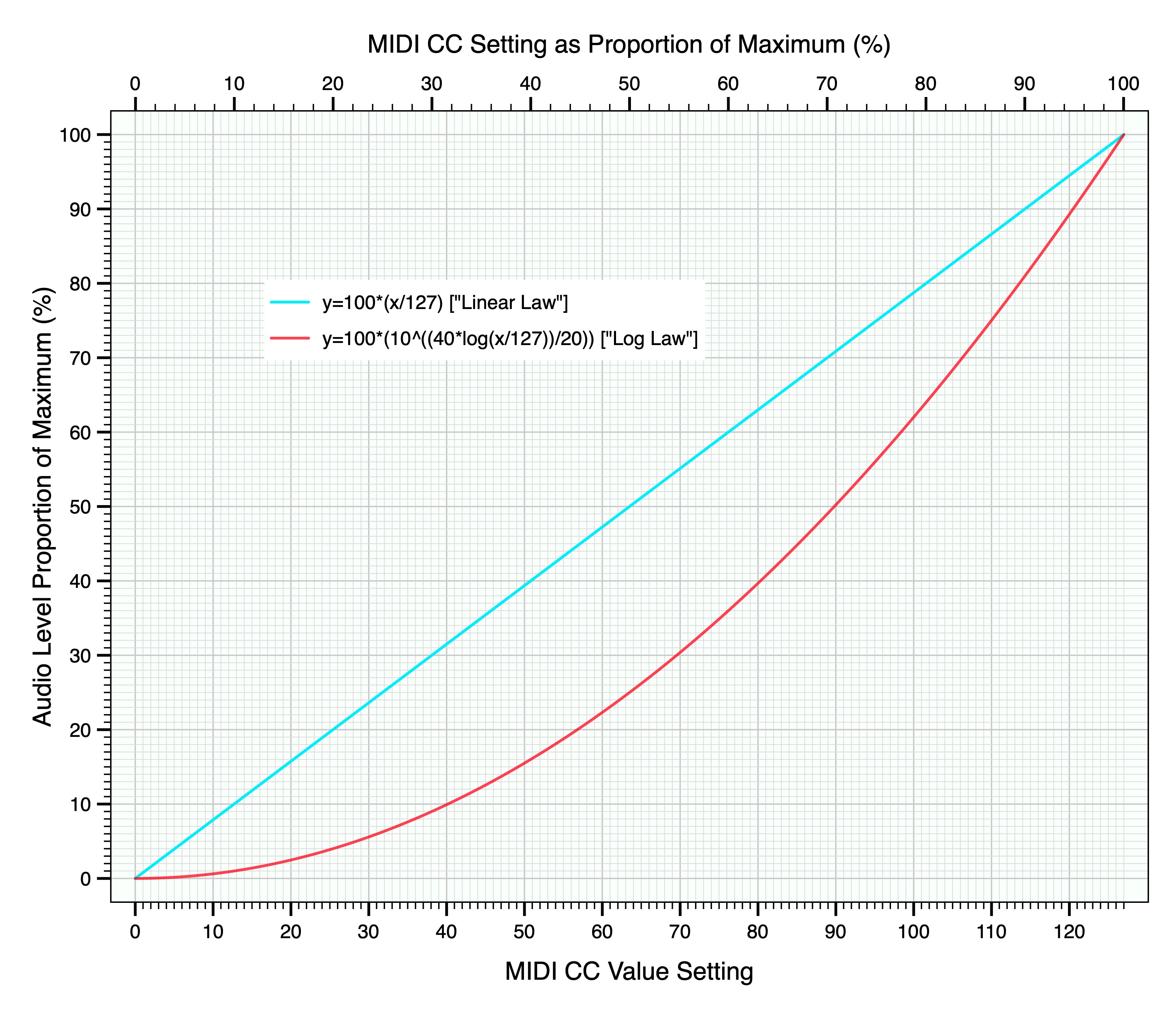
This tutorial is based on a graph (attached below) showing the most basic difference between linear-law and logarithmic-law types of control devices.
Anyone who's tinkered with audio electronics might already have discovered this result. If putting a so-called "linear" pot or slider into a circuit for controlling audio level, the useful degrees of control seem mostly crowded at one end. It ain't much use as a volume control. Manufacturers of hardware linear pots and sliders have for a very long time also made so-called "logarithmic" pots and sliders specifically for use as sound volume controls. That's because our ability to discern different levels of sound ain't linear, it's very logarithmic.
And lo and behold! In the Synchron Player, the Master Volume and Expression sliders are modelled in software to behave just like hardware faders in analogue mixing boards. Whether in hardware or in software, volume faders - with very few special exceptions - are always the "logarithmic" type; there'd be an awful lot of extremely dissatisfied customers if it were not so.
What does this difference between "linear" and "logarithmic" types of control sliders really mean in practical terms? Well for one thing it means if you set a logarithmic-type slider half way down from max, you don't get half the max level of audio as a result. But hang on, first I must define what I mean by "audio level" in this context. It's easier to explain as an amount of voltage in an analogue mixing desk. Let's say I set a volume fader to max and as a result I measure 1 Volt of audio level. Then all other audio levels can be expressed as a percentage of 1 Volt. In this case, voltage accurately represents audio level. No decibels involved, nothing up my sleeve; let's see where it takes us.
In the graph attached below, the difference is obvious. The straight blue line is what happens with a linear type of controller; the red curve represents the logarithmic type. In fact the red curve is produced by my experimentally derived and validated mathematical model of the Master Volume and Expression Faders in Synchron Player. The vertical axis might just as well be shown as audio voltage. So if I set the slider to half way, what do I get in each case? The linear-law device will give 0.5 Volts. The log-law device gives only 0.26 V. You get the idea.
But these 'voltages' or percentages of audio level aren't really of much practical use in mixing. Pro mix engineers use not only their highly experienced ears but also they live and breathe decibels, for their understanding of audio volume differences. We'd be nuts not to follow their example as best we can. So with that out of the way, we can now chuck this graph in the bin. lol. It just proves a point. (The graph and table posted above in this thread give the same basic information but in the most appropriate form for practical work. We've just had a further peak into basic theory, but not in any directly practical way.) What we've seen in the graph shows clearly that Synchron Player's Master Volume and Expression faders are like all other volume controls - which means they're logarithmic. And that type can get bloody complicated if you get right down to it, and get real ornery if you try to analyse it simplistically without correctly identifying its basic type in the first place.
Forum Statistics
194,124 users have contributed to 42,911 threads and 257,919 posts.
In the past 24 hours, we have 3 new thread(s), 14 new post(s) and 80 new user(s).


